Learn the fundamentals of Kirchhoffs Voltage Law (KVL), its applications in DC circuits, and how to effectively apply it in real-world scenarios. This in-depth guide will take you through the principles of KVL, step-by-step examples, and useful tips for mastering this essential law in circuit analysis.
Kirchhoff’s Voltage Law (KVL) is a fundamental law in electrical engineering that states the algebraic sum of the potential differences (voltages) in any closed loop or mesh in a network is always equal to zero. This principle is based on the conservation of energy in electrical circuits and is essential for analyzing and solving complex circuits.
Before diving into KVL, it’s crucial to understand the basics of direct current (DC) circuits. DC circuits consist of voltage sources, such as batteries, and various passive components like resistors, capacitors, and inductors. In a DC circuit, current flows in one direction, making it easier to analyze and apply KVL.
Loop and mesh analysis are essential techniques for applying KVL to complex circuits. A loop is a closed conducting path in a circuit, while a mesh is the simplest form of a loop, containing no other loops within it. In loop analysis, KVL is applied to every loop in the circuit, while in mesh analysis, KVL is applied to every mesh.
Kirchhoff’s Voltage Law (KVL) is a fundamental principle in electrical circuit analysis that states that the algebraic sum of all voltages around any closed loop in a circuit is zero. In mathematical terms, it can be expressed as:
ΣV = 0
where ΣV is the sum of all voltage drops across all the circuit components around a closed loop and is equal to zero.
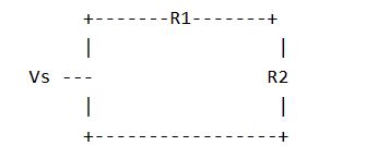
This equation can be illustrated with a simple circuit diagram as shown below:
where Vs is the voltage source, R1 and R2 are resistors.
According to KVL, the sum of all voltage drops around the loop in the above circuit must be equal to zero. Therefore, we can write:
Vs – V1 – V2 = 0
where V1 is the voltage drop across R1 and V2 is the voltage drop across R2.
Since the current flows through both resistors in series, the current through each resistor will be the same, i.e., I = I1 = I2.
Using Ohm’s law, we can write:
V1 = IR1 and V2 = IR2
Substituting these values into the KVL equation, we get:
Vs – IR1 – IR2 = 0
Rearranging the terms, we get:
Vs = IR1 + IR2
This equation shows that the total voltage supplied by the source is equal to the sum of the voltage drops across the two resistors. This is consistent with the principle of conservation of energy, which states that the total energy supplied by the source must be equal to the total energy consumed by the circuit components.
In summary, Kirchhoff’s Voltage Law is an important tool in circuit analysis that can be used to determine the voltage drops across various circuit components. By applying this principle to different loops in a circuit, the values of unknown voltages and currents can be calculated, allowing the performance and behavior of the circuit to be predicted and analyzed.
The KVL equation can be written as:
Sum of Voltage Gains – Sum of Voltage Losses = 0
or, more specifically:
Sum of V_source – Sum of (I * R) = 0
In this equation:
Let’s break down the equation further to understand how it works in a circuit:
By stating that the sum of voltage gains minus the sum of voltage losses must equal zero, KVL ensures that the conservation of energy holds true in a closed loop.
Follow these steps to apply KVL in DC circuits:
When working with complex circuits that contain multiple loops and meshes, KVL can still be effectively applied using the loop or mesh analysis techniques. For circuits with multiple voltage sources and resistors, follow these guidelines:
In a circuit containing parallel loops, KVL can be applied to each loop independently. When analyzing parallel loops, it is essential to remember that the voltage across elements connected in parallel is the same for each loop. By applying KVL to each loop and setting up a system of equations, it is possible to determine the unknown voltages and currents in the circuit.
To apply Kirchhoff’s Voltage Law in parallel loops, follow these steps:
Example Application
Consider a circuit with two resistors (R1 and R2) connected in parallel across a voltage source (V). To apply KVL to this circuit, you can create two independent loops:
Applying KVL to each loop, you will have two equations:
These equations can be solved for the loop currents (I1 and I2), allowing you to analyze the circuit behavior.
Kirchhoff’s Voltage Law is widely used in various fields, including electronics, power systems, and telecommunications. Some real-world applications include:
Here are some practical tips for mastering KVL:
Kirchhoff’s Voltage Law is a vital tool for understanding and analyzing DC circuits. By mastering the principles of KVL, loop and mesh analysis, and following a step-by-step approach to solving circuit problems, you can become proficient in this essential aspect of electrical engineering. With practice and application, you’ll be able to tackle complex circuits and real-world problems, ensuring that your knowledge of KVL remains an invaluable skill in your engineering toolkit.
Kirchhoff’s law of voltage, also known as Kirchhoff’s Voltage Law (KVL), states that the sum of the voltages around any closed loop in an electrical circuit is equal to zero. In other words, the total voltage supplied in a loop is equal to the total voltage consumed by the components within that loop. KVL is based on the principle of energy conservation and is essential for analyzing and designing electrical circuits.
Kirchhoff’s Laws, including Kirchhoff’s Current Law (KCL) and Kirchhoff’s Voltage Law (KVL), are fundamental tools for analyzing electrical circuits. They are used to:
1. Calculate unknown voltages, currents, or component values in a circuit.
2. Simplify complex circuits for easier analysis.
3. Verify the consistency of voltage and current distributions within a circuit.
4. Identify potential faults or discrepancies in circuit designs.
5. Develop a deeper understanding of circuit behavior and performance.
Kirchhoff’s Voltage Law works due to the conservation of energy principle. In an electrical circuit, energy is supplied by voltage sources (e.g., batteries, generators) and consumed by components (e.g., resistors, capacitors, inductors). KVL ensures that the energy provided by voltage sources is equal to the energy consumed by the components in any closed loop. Since no energy is lost within an ideal closed loop, the sum of the voltage drops and rises must equal zero, as described by KVL.
Kirchhoff’s Current Law (KCL) and Kirchhoff’s Voltage Law (KVL) are both fundamental principles used in circuit analysis, but they address different aspects of electrical circuits:
Kirchhoff’s Current Law (KCL): KCL states that the sum of the currents entering a junction in a circuit is equal to the sum of the currents leaving that junction. In other words, the total current is conserved at any point in a circuit. KCL is based on the principle of charge conservation and is mainly applied to analyze parallel circuits or node voltages.
Kirchhoff’s Voltage Law (KVL): KVL states that the sum of the voltages around any closed loop in a circuit is equal to zero. This law is based on the principle of energy conservation and is primarily used to analyze series and complex circuits, as well as verify voltage consistency in parallel circuits.